Call us
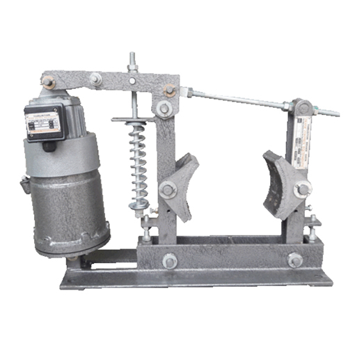
Electro Hydraulic Thruster Brake
10000.00 - 68000.00 INR/Unit
Product Details:
- Brake Type Electro Hydraulic Thruster Brake
- Click to View more
X
Electro Hydraulic Thruster Brake Price And Quantity
- 1 Unit
- 10000.00 - 68000.00 INR/Unit
Electro Hydraulic Thruster Brake Product Specifications
- Electro Hydraulic Thruster Brake
Electro Hydraulic Thruster Brake Trade Information
- 1000 Unit Per Year
- 3-4 Days
- All India
Product Description
Operating speed of movable equipment can be reduced and even the operation of the system can be stopped at required position sans any error with the help of thruster brake. A pre-stressed compression spring is used to apply braking force to the braking shoes. Thruster plays significant role in controlling compression of spring and also managing the brake. The brake can also be availed with non-automatic or pneumatic releasing controlling arrangement as per application need.
CONSTRUCTION AND OPERATION
Thruster brake comprises of friction pads equipped cast iron shoes ( a pair of) that have hinge based side as well as main arms of the brake. Each arm has hinge pin equipped base and all these pins are attached together by a tie rod on top. The tie rod is fitted with the main arm by hinge and is securely fitted by lock nut with swivel block in the side arm.
Between the main arm and the top clevis of the thruster, a hinge fitted crank lever has been installed. The main arm is also equipped with a brake spring which is pre-installed by a locknut on the lever. The braking torque depends on the pre-tension of the spring. When the thruster is not charged, force is applied on the brake shoes of the brake drum which is installed on the drive motor shaft. The break shoes are fixed for a specific position under the influence of braking force delivered by the spring. During this time, the brake is applied to prevent rotation of the drum.
With the charging of the thruster motor, applied thrust supplied by the thruster moves up the crack lever to control the arms and to keep brakes shoes away from the brake drum to discharge the braking force. With the compression of the spring, braking energy is accumulated so that it can be used for the next round of operation.
FOUNDATION
For installation of the brake, required tapped holes of precise diameter ( as per the specifications mentioned in dimension table) need to be created on the foundation. Importance needs to be given on checking whether the centerlines of the brake drum and brake coincides with each other or not. One should also verify the balance between the center height of the brake drum and the level of mounting pads.
INSTALLING BRAKE IN POSITION :
Brake shoes need to be dismantled to create required space for insertion of brake in position. For this, setting bolts as well as tie-rod nuts of the side arms need to be loosened. Slight pulling force should be applied to remove those bolts and also to create a large gap between the brake shoes. Created gap can be used for insertion of the foundation bolts and the brake shows can be positioned again on the brake drum. After completion of this entire process, tie-rods nuts, setting bolts and mounting bolts need to be fitted securely again.
INSTALLING THRUSTER ON BRAKE :
To install the thruster, it should be saturated with right amount of oil as specified in the Thruster Table. Split pins located on side split pins of one side of the brake need to be removed for installation of the thruster. Thruster hinge pins and side split pins need to be removed when the thruster is positioned on the lever of the brake and pin holes in the base. Both of the split pins need to be replaced. One should verify whether the thruster and also its thrust rod can move without any hindrance or not during non automatic puling of the crank lever.
The terminal box cover needs to be opened to establish connection between three terminals and 3 phase 415 v power supplying cables. Remove the earthing lead located on the earth terminals of the brake or the thruster. The terminal box cover needs to be replaced and the thruster is up for the operation.
ALIGNING AND SETTING OF BRAKE :
In the next stage, the brake shoes need to be aligned as per the surface of the brake drum and also as per the diameter. Tie-rods nuts need to be adjusted to promote equal griping of the brake shoes on the brake drum. Make power cables ready by recharging these. Recharging of power cables promotes upward movement of the trust rod of the thruster. With this upward movement, the shoes tend to release the brake drum that promotes the discharge of the brake. The distance between the shoes and the drum needs to be adjusted from 0.3 to 0.5. This adjustment of distance can be done simply by adjusting the setting bolts located on both the arms.
For equal and uniform liner wear it is necessary to ensure that the shoes and the arms move equally. This is done automatically by the ball on one arm and a matching vee on the other arm.
Equal movement of the arms and the shoes is required for homogeneous liner wear. This equal movement can be managed mechanically by the matching vee located on the other arm and the ball on the other arm.
Enter Buying Requirement Details
CRANE CONTROL EQUIPMENTS
All Rights Reserved.(Terms of Use)
Developed and Managed by Infocom Network Private Limited.
Developed and Managed by Infocom Network Private Limited.
